← Back to Roti Proa II Overview
Table of Contents
- Executive Summary
- Suspended Ama (Aka Bending)
- Aka Point Load (Crew Standing)
- One End Supported (Spine Bending)
- Mast Wind Loading
- Diagonal Braces (Lateral Loading)
- Wave Slam (Vertical)
- Frontal Wave Slam
- Sideways Wave Slam
- Lifting Sling (Crane Operations)
- Gunwale Load Distribution
- Ama Lift Wind Speed
- Summary Safety Assessment
Executive Summary
The RP2 structural validation suite analyzes the vessel under eleven load scenarios encompassing static loads, dynamic wave impacts, wind forces, and operational conditions. All structural tests pass with safety factors exceeding the required minimum of 2.0.
| Test | Description | Safety Factor | Result |
|---|---|---|---|
| Suspended Ama | Aka cantilever bending | 3.27 | PASS |
| Aka Point Load | Crew standing on aka | 5.74 | PASS |
| One End Supported | Spine bending | 16.5 | PASS |
| Mast Wind Loading | 25-knot wind on sail | 6.18 | PASS |
| Diagonal Braces | Lateral loading (tilted) | 33.6 | PASS |
| Wave Slam (Vertical) | 3 m/s impact, 2.5× dynamic | 4.46 | PASS |
| Frontal Wave Slam | Fore-aft impact | 5.23 | PASS |
| Sideways Wave Slam | Lateral impact | 4.46 | PASS |
| Lifting Sling | V-sling crane lift | 6.16 | PASS |
| Gunwale Loads | Load distribution to hull | 12.24 | PASS |
| Ama Lift Wind Speed | Stability limit | 21.4 knots | INFO |
1. Suspended Ama (Aka Bending)
Scenario
The outrigger (ama) loses all buoyancy support—for example, when the boat is heeled such that the ama is lifted completely out of the water, or during transport on a trailer. The full weight of the outrigger structure hangs from the akas (crossbeams), which act as cantilevers extending from the vaka (main hull).
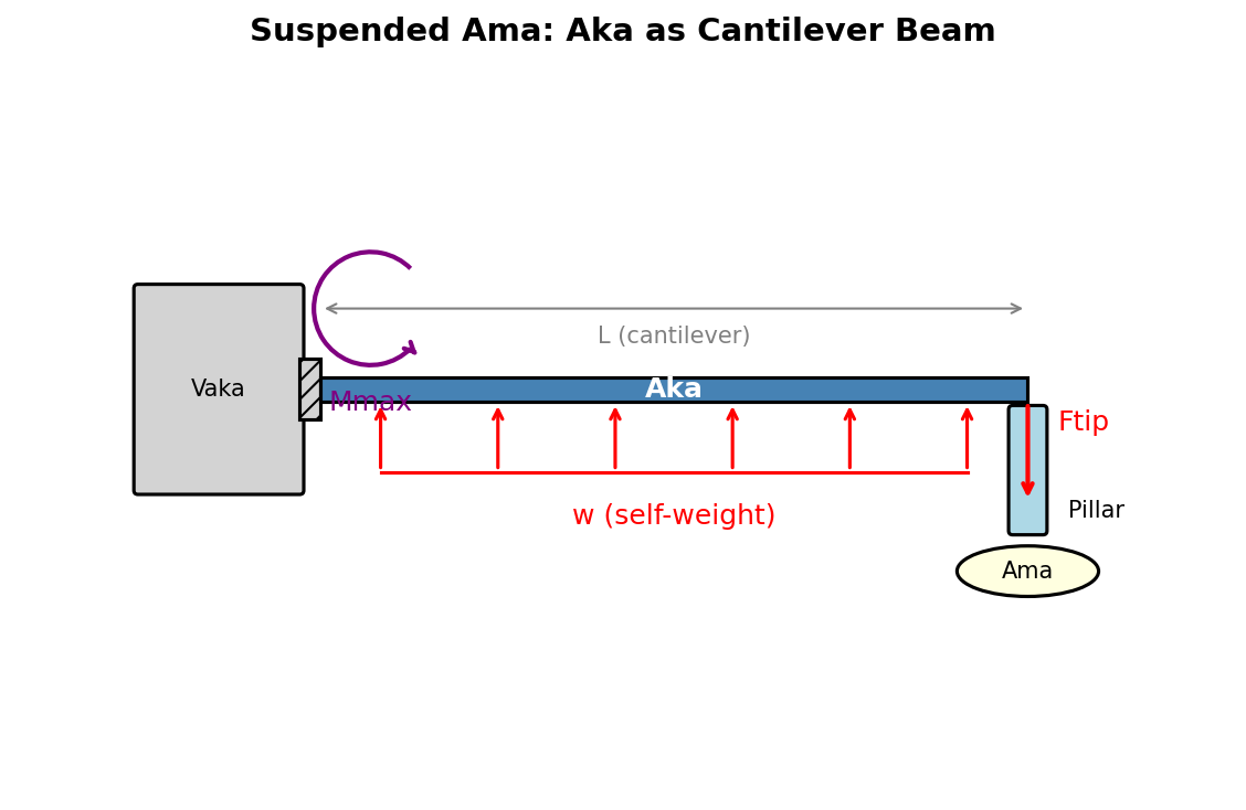
Method
Each aka is modeled as a cantilever beam fixed at the vaka gunwale. The outrigger mass is divided into:
- Tip loads: Concentrated masses at the aka tips (ama ends, solar panel edges, pillar bases)
- Distributed loads: Mass spread along the aka length (solar panels, wiring, structural elements)
The bending moment at the vaka attachment is:
\[M = F_{tip} \times L + F_{distributed} \times \frac{L}{2}\]where L is the cantilever length from vaka to pillar. Bending stress is calculated using beam theory:
\[\sigma = \frac{M}{S}\]where S is the section modulus of the aka’s rectangular hollow section (RHS).
Assumptions
- Aka section: 76.2x101.6x4.5 mm RHS
- Material: 6061-T6 aluminum (yield strength 240 MPa)
- Four akas share the load equally
- Fixed support at vaka (conservative—actual connection has some compliance)
- Strong axis (101.6 mm height) resists vertical bending
Results
| Parameter | Value |
|---|---|
| Outrigger mass | 402.8 kg |
| Cantilever length | 4.374 m |
| Maximum bending stress | 73.5 MPa |
| Maximum deflection | 122.0 mm |
| Safety Factor | 3.27 |
2. Aka Point Load (Crew Standing)
Scenario
During boarding, maintenance, or emergency situations, crew members may need to stand on the akas. This test validates the aka’s capacity to support concentrated crew weight at the worst-case location (center of span).
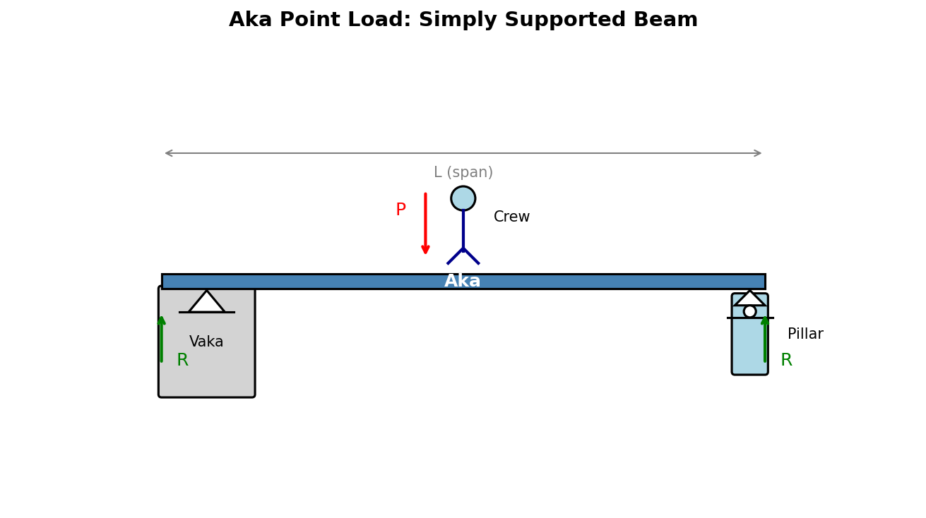
Method
The aka is modeled as a simply supported beam with:
- Support at the vaka gunwale (inboard)
- Support at the pillar (outboard, at ama)
A point load at mid-span produces maximum bending moment:
\[M_{max} = \frac{P \times L}{4}\]where P is the crew weight and L is the span between supports.
Assumptions
- Crew mass: 150.0 kg (approximately two people)
- Load position: center of span (worst case)
- Simply supported conditions (conservative for moment calculation)
Results
| Parameter | Value |
|---|---|
| Span (vaka to pillar) | 4.95 m |
| Point load | 1472 N |
| Maximum bending stress | 41.79 MPa |
| Maximum deflection | 24.3 mm |
| Safety Factor | 5.74 |
3. One End Supported (Spine Bending)
Scenario
The ama is supported at one end only (e.g., resting on a beach or dock) while the other end hangs free. This creates bending in the spine (longitudinal beam connecting the ama sections) as the akas provide intermediate support of varying stiffness.
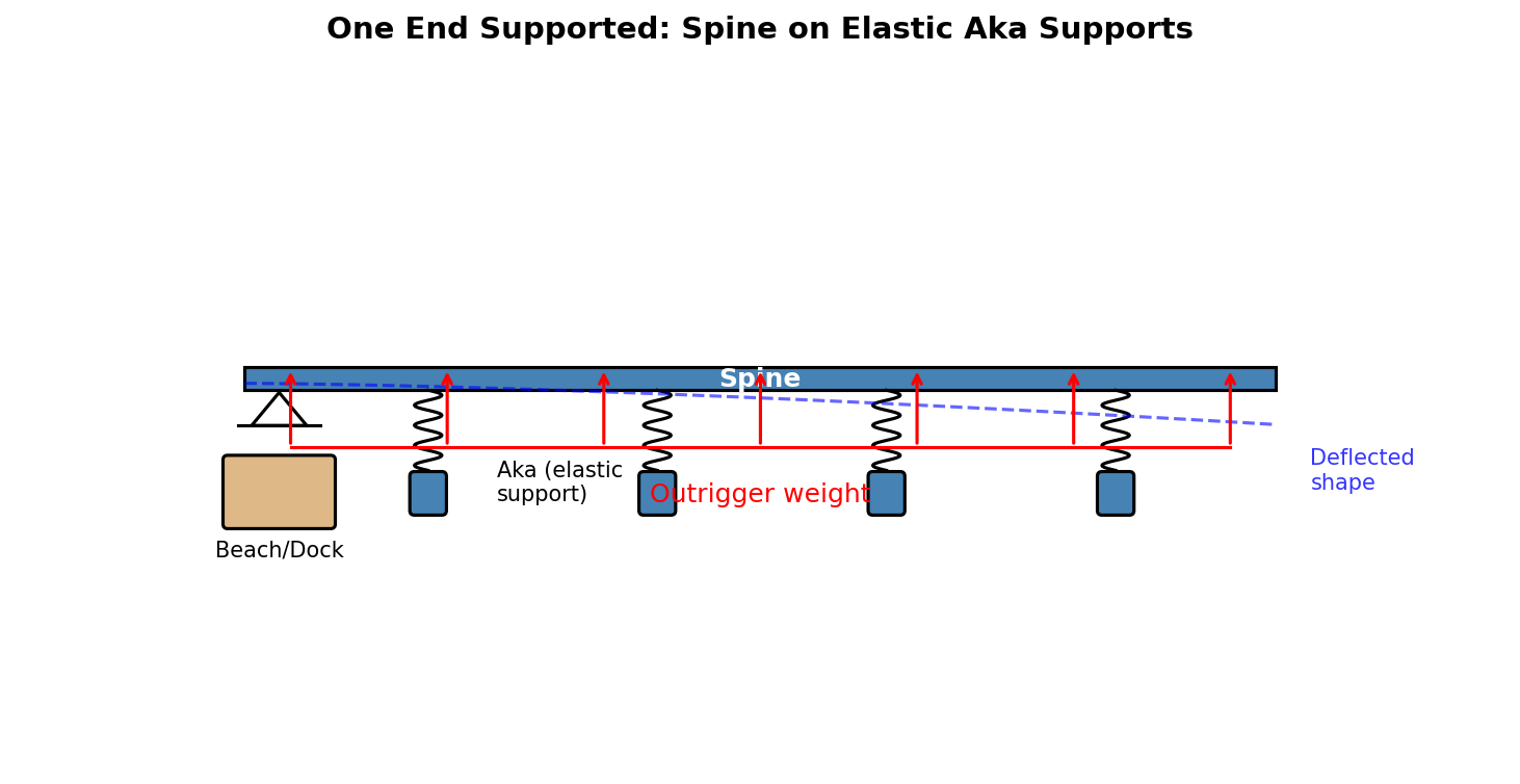
Method
The ama is modeled as a continuous beam with:
- Fixed support at one end (beach/dock contact)
- Elastic supports at each aka location (aka flexibility modeled as springs)
- Distributed load from the outrigger structure
The aka spring stiffness is derived from cantilever beam deflection:
\[k_{aka} = \frac{3EI}{L^3}\]A moment distribution analysis determines reactions at each support and the maximum bending moment in the spine.
Assumptions
- Spine section: SHS 76.2×76.2×4.5 mm aluminum
- Four akas at equal spacing along the spine
- One end fully fixed (conservative)
- Aka stiffness calculated from cantilever properties
Results
| Parameter | Value |
|---|---|
| Spine length | 5.97 m |
| Total outrigger mass | 434.77 kg |
| Maximum spine stress | 14.55 MPa |
| Safety Factor | 16.5 |
4. Mast Wind Loading
Scenario
The mast experiences significant bending loads when sailing in strong winds. The sail force acts at the center of effort (CE), creating a moment about the mast partner (deck-level support).
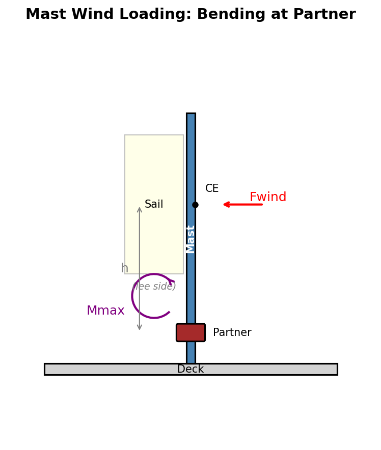
Method
Wind force on the sail is estimated per mast using the formula from ISO 12215-10 Clause 7.2 Table 5 (case b, multihull SC1):
\[F = \frac{0.72 \times V^2 \times A}{2}\]where V is wind speed in m/s and A is total sail area. The division by 2 accounts for the load being shared between two masts. The mast is analyzed for:
- Bending stress at the partner
- Shear stress at the partner
- Combined axial-bending interaction (column buckling)
- Local buckling (D/t ratio check)
The allowable bending force on the cylindrical mast is limited by bending stress at the partner:
\[F_{allowable} = \frac{\sigma_y \times S}{d_{CE}}\]where σ_y is the yield strength (240 MPa for 6061-T6), S is the section modulus, and d_CE is the distance from the partner to the sail center of effort. The section modulus for a hollow cylindrical tube is:
\[S = \frac{\pi (D^4 - d^4)}{32 D}\]where D is the outer diameter and d = D - 2t is the inner diameter. These are standard beam theory formulae applied to the mast geometry, as permitted by ISO 12215-10 Clause 5.3 (which allows any relevant engineering method for stress evaluation).
Assumptions
- Wind speed: 25.0 knots
- Sail perpendicular to wind (maximum force)
- Mast section: 152.4 mm diameter × 6.35 mm wall
- Material: 6061-T6 aluminum
- Unstayed mast (no shrouds or stays)
- Wind force per ISO 12215-10 Clause 7.2 Table 5; stress evaluation per Clause 5.3
Results
| Parameter | Value |
|---|---|
| Sail area | 30.25 m² |
| Wind force | 1801 N |
| Bending stress at partner | 38.8 MPa |
| D/t ratio | 24.0 (< 50 OK) |
| Safety Factor | 6.18 |
5. Diagonal Braces (Lateral Loading)
Scenario
When the boat is tilted (on its side during beaching, or inverted after a capsize), the outrigger weight creates lateral forces on the diagonal braces connecting the pillars to the akas. These braces must resist both compression and tension depending on orientation.
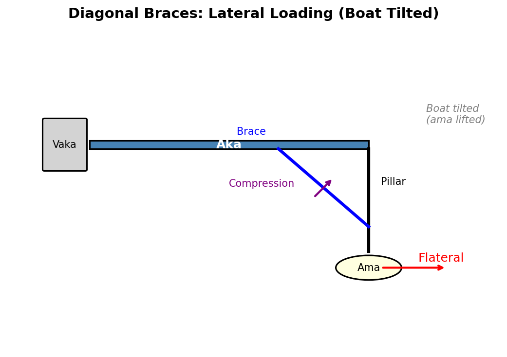
Method
The lateral force equals the outrigger weight when the boat is fully on its side:
\[F_{lateral} = m_{outrigger} \times g\]This force is distributed among all diagonal braces. Each brace is checked for:
- Compression: Euler buckling and compressive yielding
- Tension: Tensile yielding
The critical mode is Euler buckling for slender compression members:
\[\sigma_{cr} = \frac{\pi^2 E}{(L/r)^2}\]where L/r is the slenderness ratio.
Assumptions
- Brace section: SHS 25.4x3 mm
- Brace length: 815 mm
- Brace angle: 45.0° from horizontal
- Number of braces: 8
- Pin-ended connections (conservative for buckling)
Results
| Parameter | Value |
|---|---|
| Outrigger mass | 402.8 kg |
| Force per brace | 699 N |
| Slenderness ratio | 88 |
| Governing mode | buckling |
| Safety Factor | 33.6 |
6. Wave Slam (Vertical)
Scenario
When sailing in waves, the ama can slam into the water surface with significant velocity, creating impulsive hydrodynamic loads. This test analyzes vertical wave slam—the ama impacting the water from above.
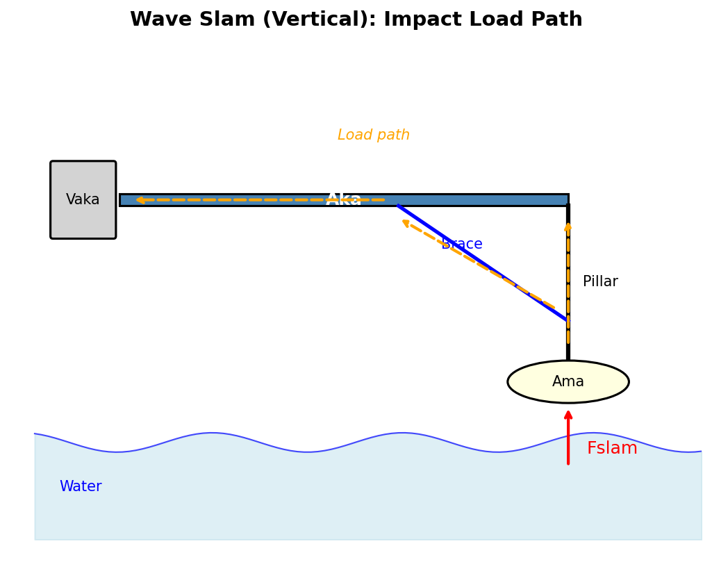
Method
Slam pressure is estimated using the water hammer formula:
\[P = \frac{1}{2} \rho V^2 C_p\]where V is impact velocity and C_p is a pressure coefficient. A dynamic amplification factor accounts for structural response to impulsive loading.
The load path is: wave → pillars → diagonal braces → akas → vaka
The aka is modeled as a propped cantilever with:
- Fixed support at vaka
- Elastic spring support at diagonal brace attachment
Assumptions
- Impact velocity: 3.0 m/s
- Dynamic factor: 2.5×
- Slam coefficient: 1.5
- Effective ama area: 1.72 m² (partial immersion)
- Braces provide elastic support to akas
Results
| Parameter | Value |
|---|---|
| Slam pressure | 6.92 kPa |
| Total slam force | 29759 N |
| Aka stress | 41.99 MPa (SF=5.72) |
| Brace stress | 19.57 MPa (SF=4.46) |
| Spine stress | 53.62 MPa (SF=4.48) |
| Governing Component | diagonal_braces |
| Safety Factor | 4.46 |
7. Frontal Wave Slam
Scenario
The ama encounters a wave head-on, creating a fore-aft impact force. This load is resisted by the X-shaped cross-braces between neighboring pillars.
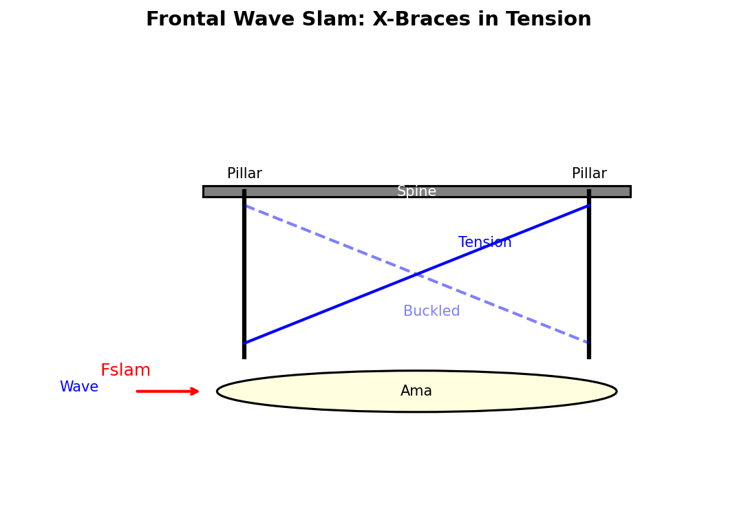
Method
Frontal slam force is calculated from the ama’s cross-sectional area. The X-braces work as a tension-only system: when loaded, the compression diagonal buckles (due to extreme slenderness), and the tension diagonal carries the full load.
Brace slenderness ratio determines behavior:
\[\lambda = \frac{L}{r} > 100 \implies \text{tension-only behavior}\]Assumptions
- Ama frontal area: 0.1075 m² (circular cross-section)
- Cross-brace diameter: 5 mm (solid rod)
- Brace length: 2060 mm
- Number of X-brace pairs: 3
- Slam coefficient: 2.0 (blunt body)
Results
| Parameter | Value |
|---|---|
| Frontal slam force | 2480 N |
| Slenderness ratio | 1648 |
| Mode | yielding (tension-only) |
| Tension per brace | 901 N |
| Stress | 45.91 MPa |
| Safety Factor | 5.23 |
8. Sideways Wave Slam
Scenario
A wave strikes the ama from the side (athwartships), creating lateral forces. The diagonal pillar braces resist this load in compression.
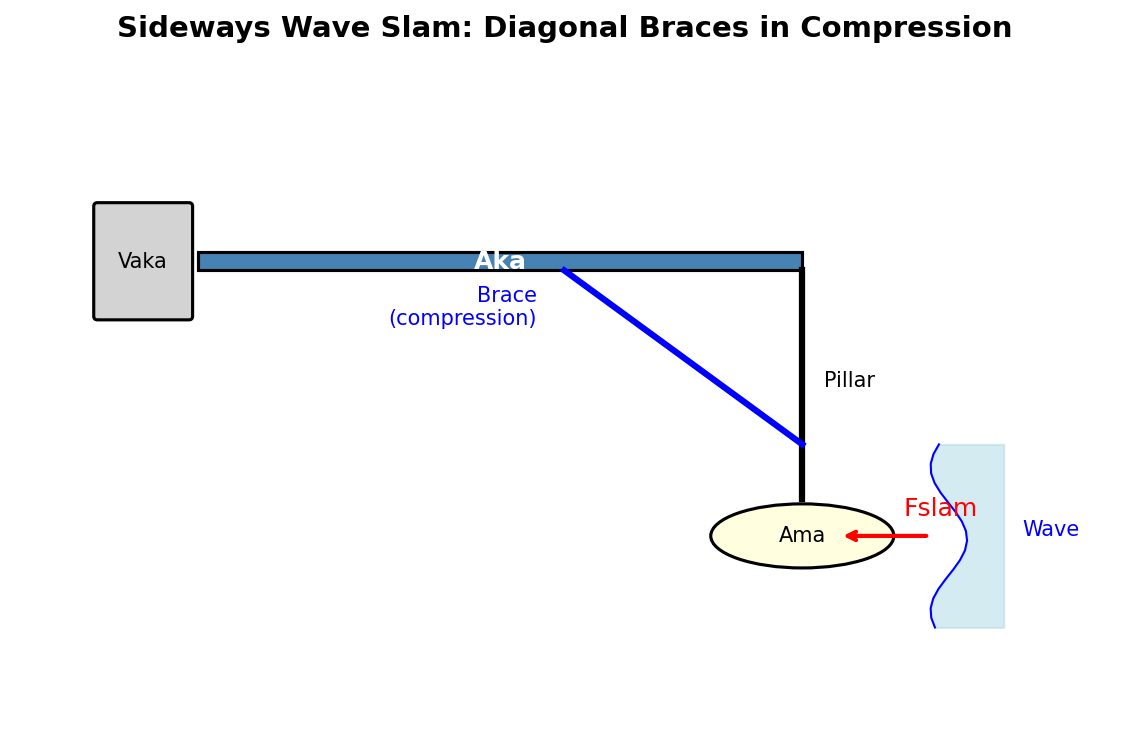
Method
The lateral slam force is calculated from the ama’s projected side area (length × diameter). The diagonal braces take the horizontal component of this force.
Assumptions
- Same slam parameters as vertical wave slam
- Diagonal braces at 45° take horizontal load
- Buckling governs for compression braces
Results
| Parameter | Value |
|---|---|
| Side slam force | 29759 N |
| Force per brace | 5261 N |
| Euler buckling load | 23468 N |
| Safety Factor | 4.46 |
9. Lifting Sling (Crane Operations)
Scenario
The boat is lifted by crane for launch, haul-out, or transport. A V-sling configuration uses 4 hooks, each connected by two ropes to neighboring akas, distributing the load across all structural elements.
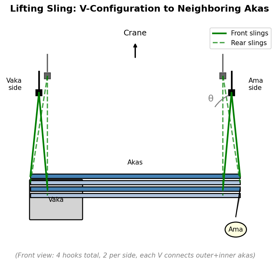
Method
The V-sling creates 8 attachment points. Each rope carries a fraction of the vertical load, with increased tension due to the V-angle:
\[T = \frac{F_{vertical}}{\cos(\theta)}\]Checks include:
- Aka bending (all 4 akas participate)
- Local stress at sling attachment points
- Rope/sling tension capacity
- Global boat bending between supports
Assumptions
- Total boat mass: 2350.0 kg
- V-angle from vertical: 25.3°
- Sling type: 50mm polyester flat sling (WLL 2000 kg)
- Aka spacing: 1.89 m
Results
| Component | Stress/Load | Safety Factor |
|---|---|---|
| Aka bending | 35.82 MPa | 6.7 |
| Sling attachment | 22.71 MPa | 10.57 |
| Rope tension | 3187 N | 6.16 |
| Global bending | 0.76 MPa | 32.99 |
| Governing | rope_tension | 6.16 |
10. Gunwale Load Distribution
Scenario
The akas transfer all outrigger loads to the vaka through the gunwales. This test validates that the wooden gunwales (3” × 2”, fiberglass-bonded to the hull) can carry and distribute the concentrated aka loads.
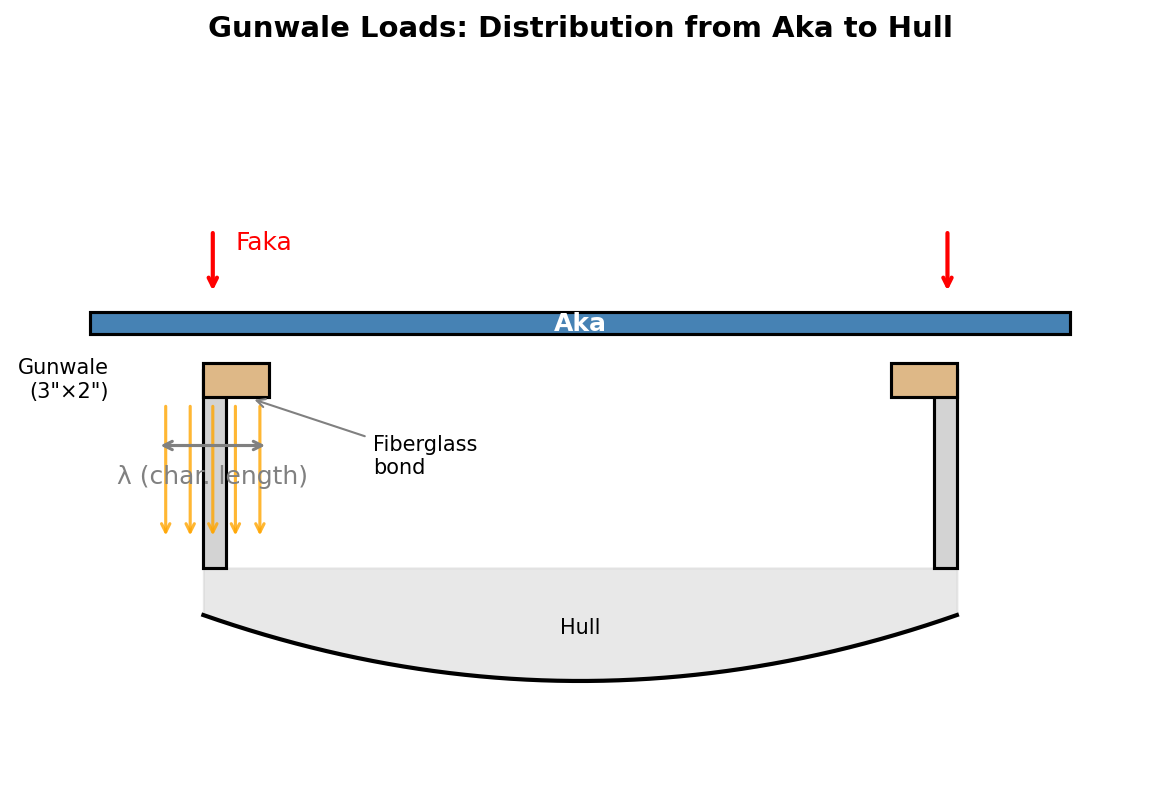
Method
The gunwale is modeled as a beam on elastic foundation. The characteristic length over which load spreads is:
\[\lambda = \left(\frac{4EI}{k}\right)^{0.25}\]where k is the foundation stiffness (hull skin supporting the gunwale).
Checks include:
- Gunwale bending stress
- Bearing stress (wood perpendicular to grain)
- Bond shear (fiberglass joint to hull)
Assumptions
- Gunwale section: 76.2 × 50.8 mm
- Material: Douglas fir or similar (allowable bending 50 MPa, bearing 10 MPa)
- Fiberglass bond allowable shear: 5 MPa
- Design load: wave slam (governs over static suspended ama)
Results
| Check | Stress | Allowable | Safety Factor |
|---|---|---|---|
| Gunwale bending | 4.09 MPa | 50 MPa | 12.24 |
| Bearing (perp. grain) | 0.38 MPa | 10 MPa | 26.01 |
| Bond shear | 0.2 MPa | 5 MPa | 24.86 |
Load Distribution: Aka spacing (1890 mm) is 4.2× the distribution length (450 mm), so loads are independent.
11. Ama Lift Wind Speed (Informational)
Scenario
This informational calculation determines the wind speed at which the heeling moment (wind from the ama side) equals the maximum righting moment, causing the ama to lift clear of the water.
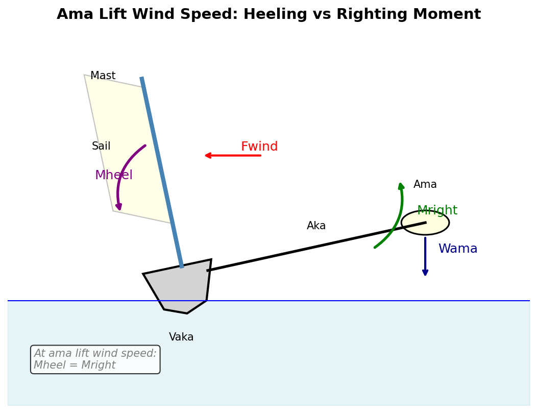
Method
The heeling moment from wind force is:
\[M_{heel} = F_{wind} \times h_{CE}\]where h_CE is the height of the sail’s center of effort above the heeling axis. This is compared against the maximum righting moment from the GZ curve analysis.
Results
| Parameter | Value |
|---|---|
| Total sail area | 60.5 m² |
| CE height | 2.7 m |
| Max righting moment | 13957 N·m |
| Ama lift wind speed | 21.4 knots |
Note: This is the theoretical wind speed with full sail and no crew weight adjustment. In practice, crew can move to windward and sails can be reefed.
Summary Safety Assessment
Overall Structural Integrity
The Roti Proa II structural design passes all validation tests with safety factors exceeding the required minimum of 2.0. The structure demonstrates adequate strength and stiffness for:
- Normal operations: Sailing, motoring, anchoring, beaching
- Dynamic events: Wave slam impacts from multiple directions
- Handling operations: Crane lifting, trailer transport
- Emergency scenarios: Capsize, crew on crossbeams
Critical Load Paths
- Outrigger to Vaka: Loads transfer through akas → gunwales → hull
- Wave Impact: Forces distribute through pillars → braces → akas
- Wind Loads: Sail forces transfer through mast → partner → hull
Recommendations
- Inspection Points: Regularly inspect aka-gunwale connections, diagonal brace welds, and fiberglass bonds
- Lifting Operations: Use the V-sling configuration with 4 hooks to neighboring akas
- Wave Slam Limits: The 3 m/s impact velocity represents moderate conditions; avoid extreme wave encounters
- Wind Limits: The mast is validated for 25 knots; reef sails in stronger conditions
Validation Software
This report was generated automatically from the parametric CAD model using the validate-structure module. Source code: github.com/shipshape-marine/solar-proa
| ← Back to RP2 Overview | View Stability & Buoyancy Analysis → |